Connectivity of single elements
In this section we collect the connectivity tables of the individual elements that cn be used to build a data chain. Combining the tables one can form a complete start-to-end connectivity. This is done in the next section.
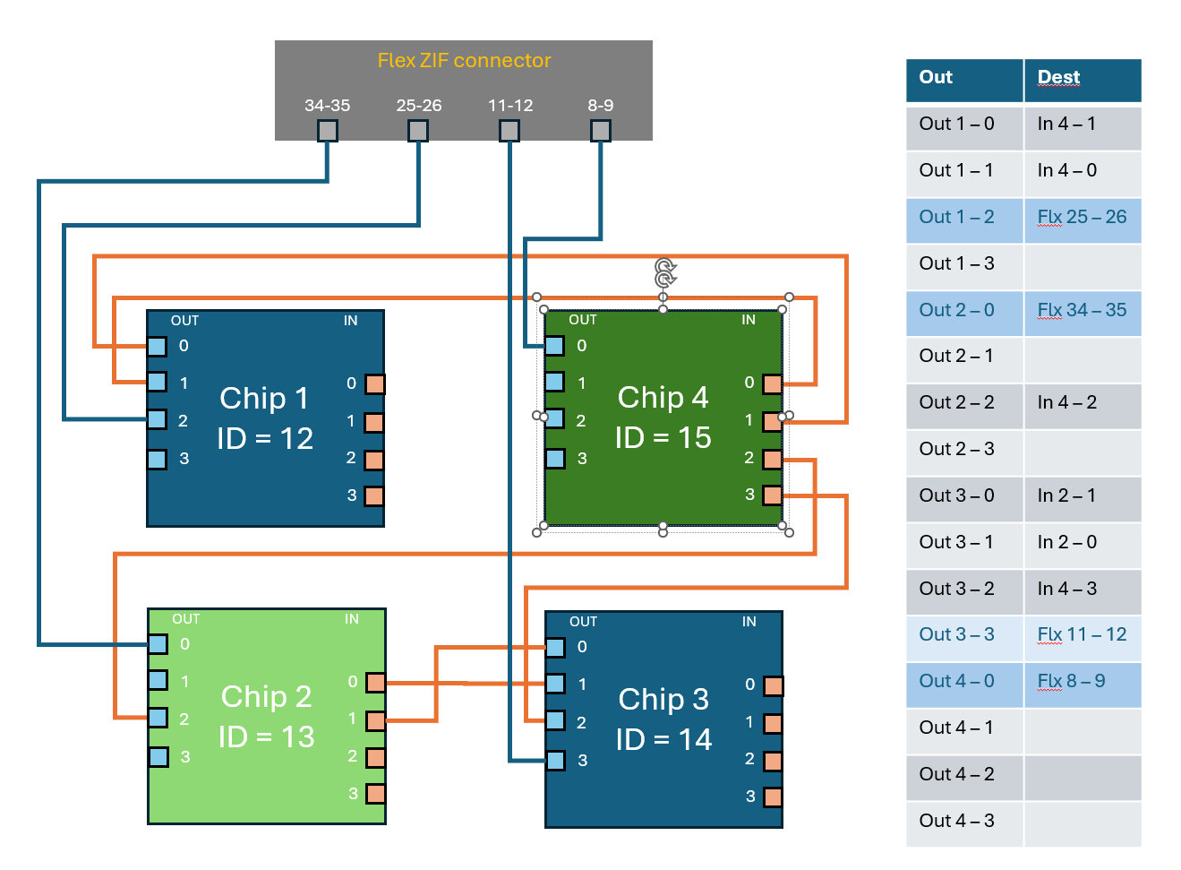
Quad L2-L4 flex
The figure shows the connection of FE chips input and output data lanes as implemented in the quad flex V3.3 (schematics here).
Triplet R0.5 flex
(schematics here).
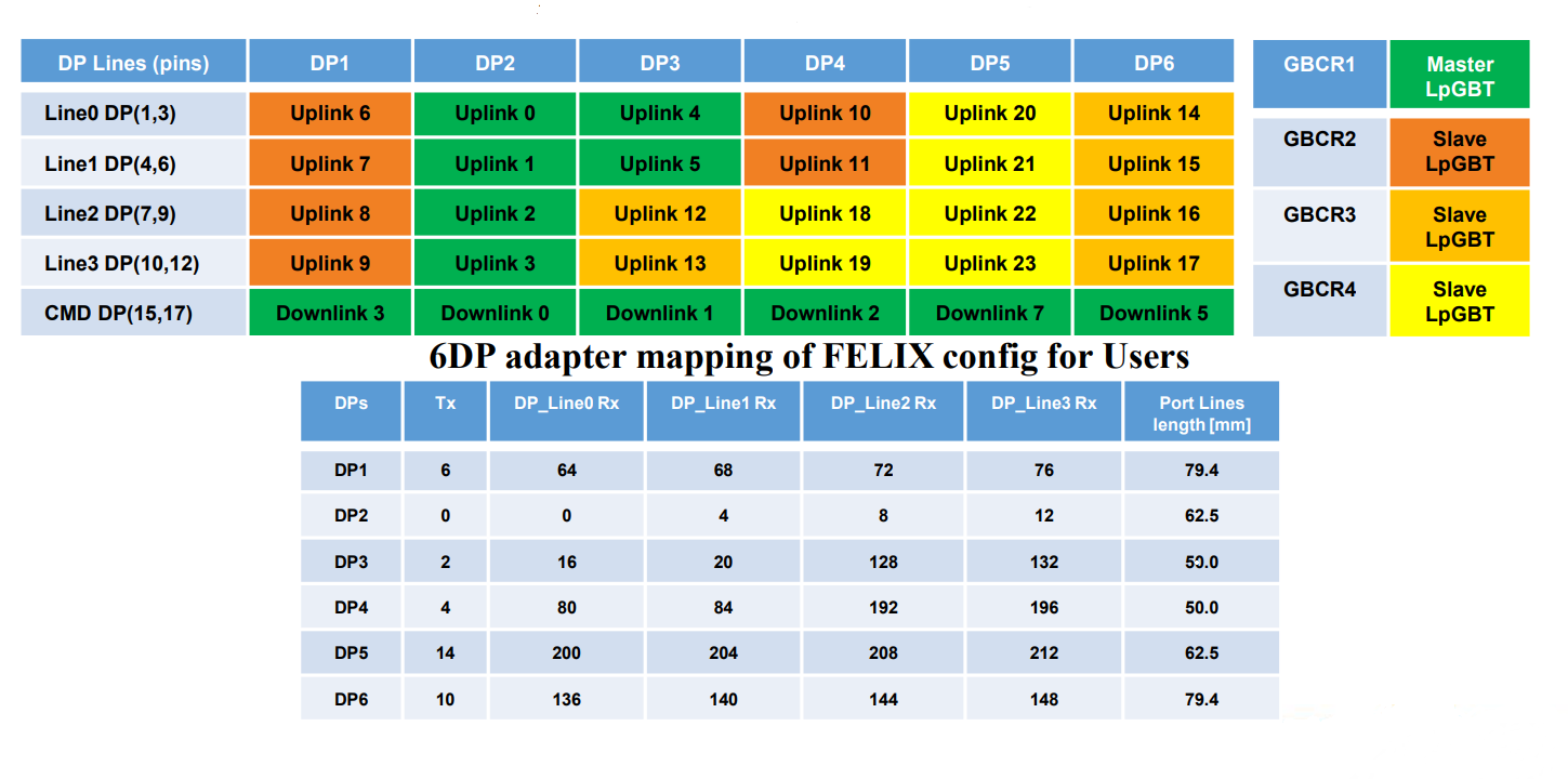
"Zaza" board
Connections between the 6 DisplayPort connectos and the Optoboard links/e-links ad implementd in the 6 DP adapter board V1.0 (full doc here).
Optobox / Optoboard
Our optobox is of "mirrored" flavor. At the moment, it contains three optoboards, as illustrated here:
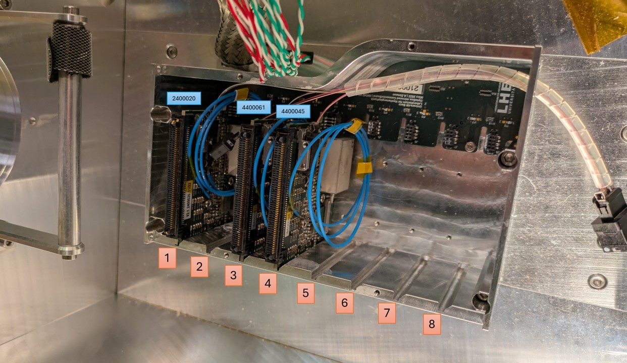
The default optobox configuration recommended for loading sites uses slots 3, 4 ,5 and 6. This configuration howerever uses two shuffling assemblies and we have just one at the moment. Moreover, one of the four optoboards allocated for Genova is currently used in Frascati. We then decided to use optobox slots 1, 3 and 4 and a single shuffling assembly. The missing optoboard will go in slot 6.
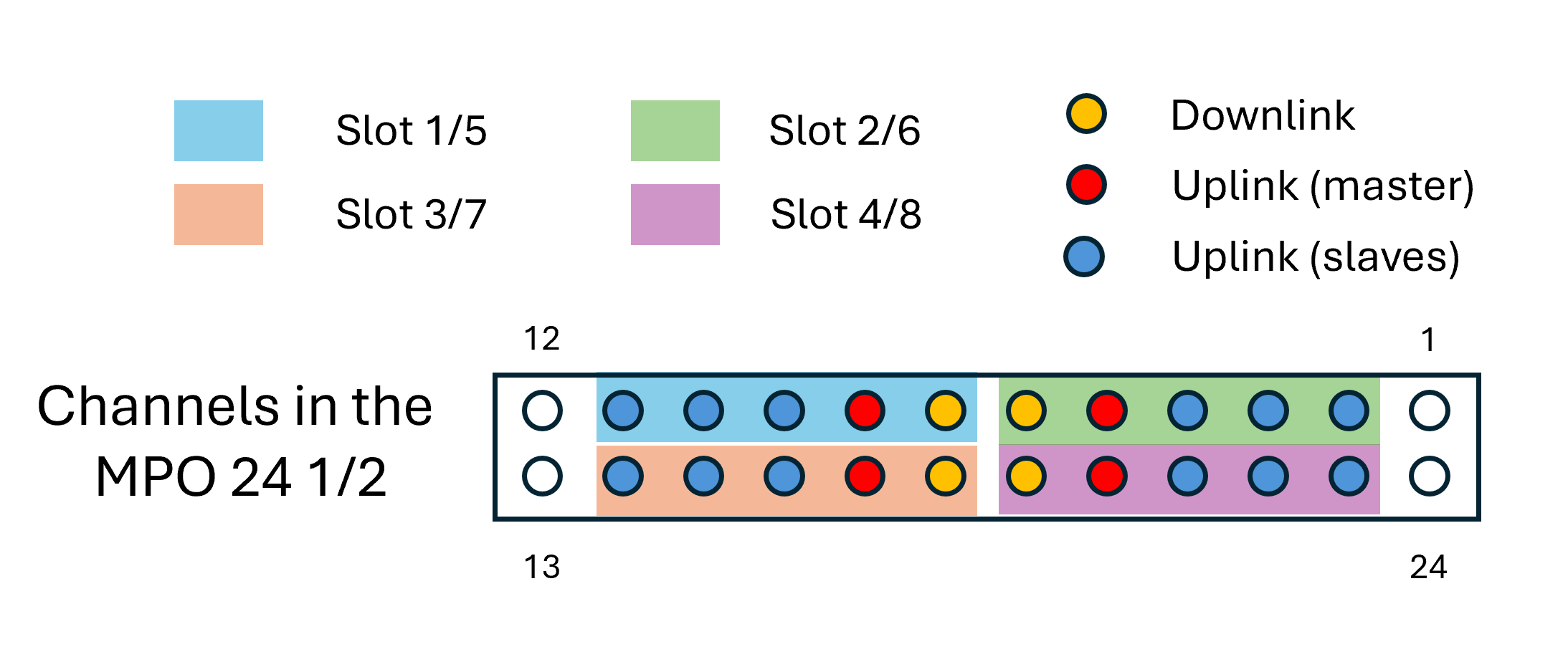
The mapping between the individual channels in the optoboxes and the output MPO24 - 24 x LC shuffle cable depends on the orientation of the individual connectors. The map implemented in our optobox is shown here:
Optoboards to FELIX - fiber mapping
The detailed mapping from the individual optoboard cahnnels to FELIX is reported in the following table:
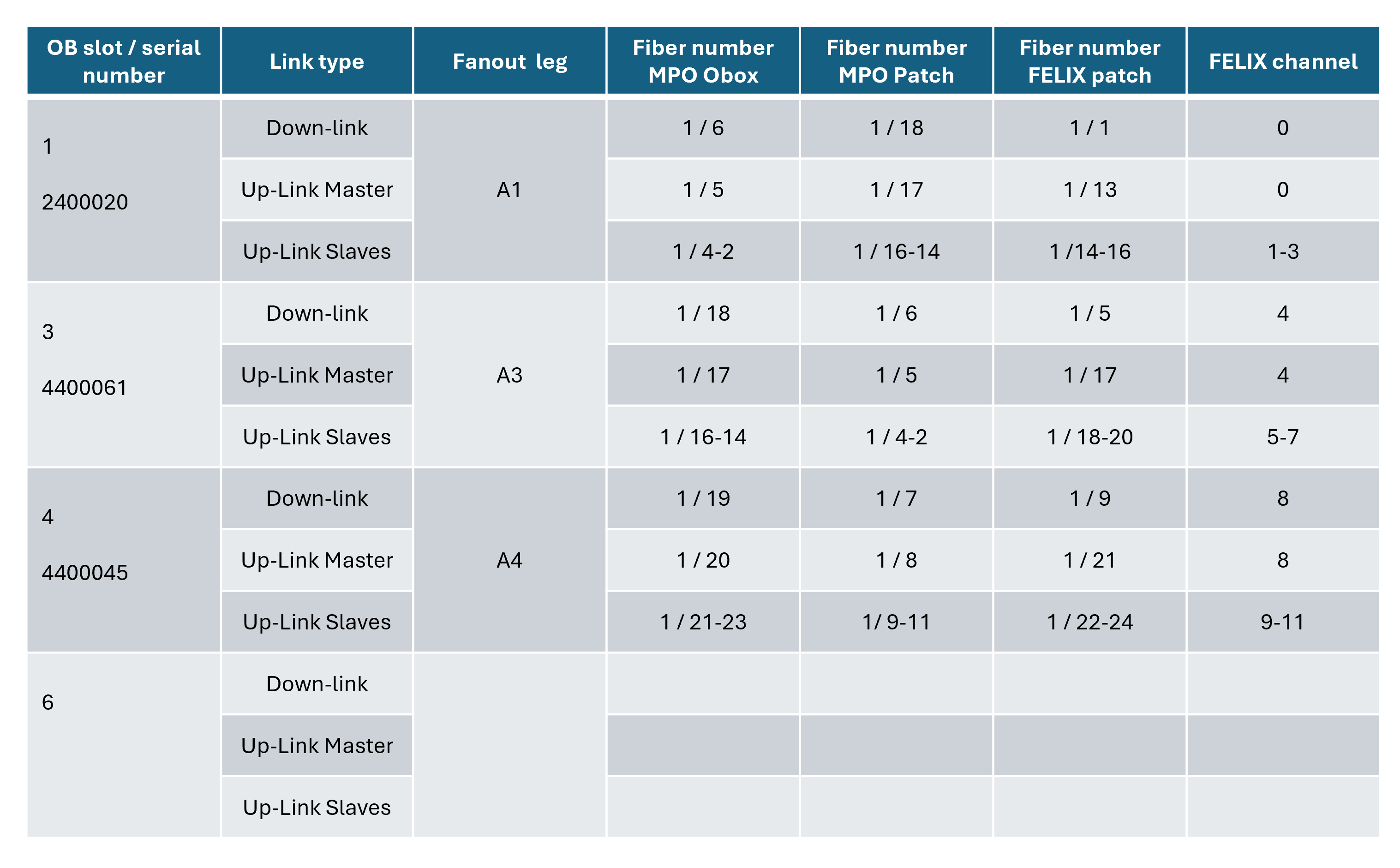
Only one fiber patch cable set is presently availalbe, so only one MPO24 FELIX connector is used. It is connected to dev 0 (links 1-12). Since we have three optoboards and a total of 3x4 = 12 uplinks, the input connections on dev 0 are all used. This requires the adoption of a 24 ch FELIX firmware (12 ch firmware uses 6 channes on dev 0 and 6 on dev 1).